About Non-Planar Views
You can create projections based on a selected sphere or cylinder as well as extract data from a curved plane. This means that 2D views are not limited to simple slices through an object. In the Non-Planar View mode, round or curved objects can be unrolled or projected along their surface in a 'flat' 2D view. This provides for the characterization of internal geometries, for example in parts built by additive manufacturing (AM) or other processes.
You should note that the Non-Planar View mode is a standard feature for all Dragonfly licenses and that you can wrap all of the structured grids within a view — such as image data, regions of interest, and multi-ROIs — inside a sphere or cylinder or that intersect with a curved plane and then unwrap them in a non-planar 2D view.
Non‐planar view (right) unwrapped from a cylindrical surface

Cylindrical projections, as shown above, represent meridians as straight, evenly-spaced vertical lines and circles of latitude (parallels) as straight horizontal lines. In general, this projection is best for objects which can be completely enclosed and visible within a cylinder, without projecting or hollow parts.
Two non-planar views — Sinusoidal and Equirectangular — are available for projecting the surface of a sphere to a flat image. You should note that spherical maps take into account the sphere’s curvature, and each latitude line becomes evenly spaced. In general, these projections are best for objects which can be completely enclosed and visible within a sphere, without projecting or hollow parts. Examples of the available spherical projections are shown in the following screen captures.
Sinusoidal (top right) and Equirectangular (bottom right) non‐planar views unwrapped from a spherical surface

Sinusoidal… Is a pseudocylindrical, equal area projection in which equally spaced parallels and a central meridian are straight lines and the other meridians are sinusoidal curves, bulging away from the central meridian and equally spaced. Sinusoidal projections present accurate area and distance at every parallel and at the central meridian, while distortion increases at the outer meridians and at high latitudes. This is illustrated in the following diagram:
Distortion at the outer meridians and at high latitudes
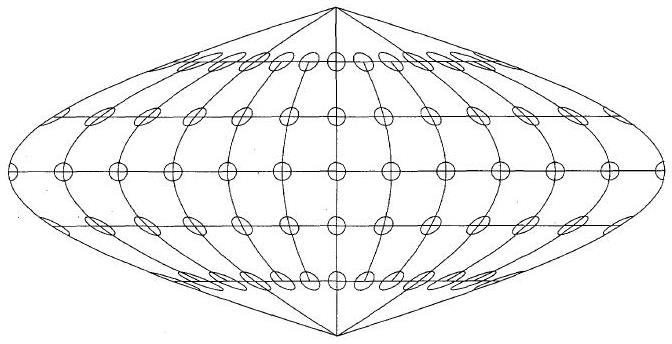
As shown in the above diagram, the equator and the central meridian are the most accurate parts of the projection, while distortion increases with distance from those parts.
Equirectangular… Also called the equidistant cylindrical projection, an equirectangular projection is a simple projection that maps meridians to vertical straight lines of constant spacing (for meridional intervals of constant spacing), and circles of latitude to horizontal straight lines of constant spacing (for constant intervals of parallels). The projection is neither equal area nor conformal because of the distortions introduced.
A number of configured actions and keyboard shortcuts are available for non-planar views. The default settings for these actions are listed in the following table.
| Action | Key | Mouse |
|---|---|---|
| Add or remove control points from Visual RBF rectangle | Left Ctrl | Left mouse |
| Change projection mode | - | Left mouse |
| Manipulate the cylinder Theta offset | - | Left mouse |
| Manipulate the sphere north pole position Phi | - | Left mouse |
| Manipulate the sphere north pole position Theta | - | Left mouse |
